ICON and Aircraft Research Association (ARA) enter into a strategic partnership to serve the Global Aerospace Industry

Windsor, Bedford, UK, 27 September 2012

ICON and ARA, two of the UK’s leading innovators in the development and support of Computational Fluids Dynamics (CFD) processes, are pleased to announce that they have signed a strategic partnership. Their joint expertise in CFD technology development, along with ARA’s ability to combine wind tunnel testing and the complementary services of model design, component manufacture and aerodynamic analysis, means the partnership can offer high quality, fully validated products to the aerospace industry.

ICON, who since 1992 has supplied high value-added, supported CFD-driven design technologies to a variety of industries worldwide, including AIRBUS and its component suppliers, is excited to be working on collaborative software technologies with ARA, who will be able to validate the civil and defence applications using their established test facilities and extensive experience in aeronautical applications.

Bob Bosher, Chief Operations Officer at ARA said “We are delighted to be working with ICON on mutual technology collaborations and service offerings which will be provided globally to civil and defence aircraft manufacturers”.

David Green, Commercial Director at ICON, stated that: “ARA was a natural choice as a partner with its extensive experience in working with global aerospace manufacturers in a number of different technology areas, combined with a company culture that fits well with ICON – focussed upon providing excellent customer service. We are looking forward to this collaboration”.

 About ARA (www.ara.co.uk)

Aircraft Research Association was established in 1952 as a wind tunnel test centre for the UK aircraft industry by 14 British aerospace companies. Today, this independent non-profit distributing research and development company has gained worldwide recognition as a centre of excellence, providing the aerospace industry with high quality aerodynamic and related services and facilities to support the design, development and through-life upgrades of commercial aircraft, military aircraft and defence system programmes. For more information visit www.ara.co.uk or contact Nigel Corby on 01234 350681, business@ara.co.uk

 About Icon Technology & Process Consulting Limited (www.iconcfd.com)

ICON is a privately-owned CFD technology company formed in 1992. ICON’s strategy is as pertinent today as it was then: to provide high-quality independent advice and expertise in process, technology and services.

ICON has extensive experience in the use of proprietary software for CFD simulation and optimization, together with expertise in developing and supporting open source CFD technologies. ICON supports customers from a variety of industries including aerospace, automotive, consumer goods, energy and processing sectors.

The company head-quarters are in Windsor, UK with further offices throughout Europe and the USA (Cincinnati, OH).

For further information please visit iconcfd.com/contact.

ICON reaction to ESI® acquisition of OpenCFD® Limited and OpenFOAM® Trademark

September 12, 2012, Windsor UK.

ICON see this latest acquisition by ESI of OpenCFD Limited as another reinforcement of the widely accepted view that open source CFD technology and related services, are now an integral and invaluable part of industrial engineering simulation.

It is too early to say how the acquisition of OpenCFD Limited and the OpenFOAM trademark by ESI will be perceived by the CFD community. However, as for the last 20 years, at ICON we will remain completely committed to serving our clients’ interests in our specialist and sole technology focus of CFD processes, ensuring greatest value and productivity, to drive our customers’ product and process design.

We continue to welcome any collaboration that takes CFD forward, with our principal aim being to ensure the delivery of high quality CFD process to our rapidly growing client base. ICON remains a preferred independent CFD solutions provider to industry – developing and supporting CFD process, based upon both open and proprietary technologies.

As a privately-held company, without public shareholders interests to satisfy, ICON can and will continue act independently and to re-invest income into the CFD processes that add greatest value for it’s customers. Working together with various third-party partners in technology, territory support provision and hardware, ICON will continue to strive to provide the greatest value from, and impact upon, CFD-related processes.

OpenFOAM® and OpenCFD® are registered trademarks of ESI®

Manufacturing Processes & Consumer Products

iconCFD News Cast – 04/2012 – Adjoint Optimization in iconCFD I/II

iconCFD Optimize 2.1.1 is an extension module to iconCFD. It provides a streamlined process for the solution of optimal design problems applying ICON’s latest developments in the field of continuous adjoint optimization.

This News Cast gives a short introduction to the theory of CFD-based adjoint optimisation and presents the capabilities for adjoint topology optimization available in iconCFD Optimize 2.1.1. A second News Cast will describe adjoint shape optimization functionalities.

Adjoint Optimization

The goal of optimization in CFD is to minimize a cost function (also objective function), J (α,v,p), subject to a converged solution of the Navier Stokes Equations, R (α,v,p), in the flow domain, Ω,


by finding optimal values for a set of design parameters, α.

The adjoint method consists in using Lagrange multipliers to enforce the constraint of the Navier Stokes Equations on the optimization problem (see http://en.wikipedia.org/wiki/Lagrange_multiplier).

L (α,v,p) is the augmented cost function; the adjoint velocity, u, and the adjoint pressure, q, are the Lagrange multipliers of the problem.

Every optimal point must fulfil 3 conditions:

– A converged flow field must be obtained by solving the Navier Stokes equations:  

– While α is treated as constant, an optimal point must be at a critical point of the augmented cost function:

The adjoint equations are derived from this condition (described in detail by Petropoulou [1]). They are a set of partial differential equations, from which the adjoint velocity and pressure are obtained.

– When the first two conditions are fulfilled,  may be computed. This term expresses the sensitivity of the cost function with respect to the design variables. For optimal design parameters this sensitivity also becomes zero: 

The major advantage of the adjoint technology over other gradient-finding methods is that the effort for computing the sensitivities (gradients) is relatively small and independent of the number of design variables.

Adjoint topology optimization in iconCFD Optimize 2.1.1

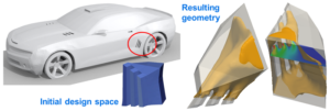
Topology optimization is used to compute an optimal geometry for internal flow problems, such as ducts. The user simply specifies the available design space. During the optimization the sensitivity information is used to iteratively block cells around the optimal flow path.

Figure 1: Topology optimisation of internal ducting system, minimizing power dissipation.

adjointSimpleFoam is a Reynolds averaged, turbulent, incompressible, steady state adjoint solver. It can be used with a variety of cost functions:

– Power dissipation (pressure loss)
– Drag
– Lift
– Flow uniformity at a surface or in a volume
– Mass flow rate
– Shear velocity (for acoustics)
– Turbulent content in a volume (for acoustics)
– Swirl in a volume

Simulations with adjointSimpleFoam can easily be set-up with the iconCFD 2.1.1 pre-processing tools.

For problems where the internal flow domain is embedded in a larger, complex geometry (i.e. a cooling duct in a car underhood), solving the optimization problem in isolation, may result in an overall non-optimal solution. In order to efficiently and accurately solve this type of problem ICON has developed the adjointSubCase technology.

With the adjointSubCase function object it is possible to solve the adjoint optimization problem locally, while solving the flow equations globally (using for example simplePorousFoam) and therefore retaining the feedback from the external flow in the optimization loop.

This method ensures appropriate flow conditions at the inlets and outlets of the sub-domain, without having to solve the adjoint equations in the whole simulation domain. Since the adjoint sub-case is created automatically at the initialisation of the simulation run, adjointSubCase is as easy to set up as any other function object.

Figure 2: Click here to watch video about adjointSubCase topology optimisation of brake cooling ducts.

For further details please follow this link to contact us.

[1] S. Petropoulou, “Industrial Optimisation Solutions Based On OPENFOAM® Technology” European Conference on Computational Fluid Dynamics ECCOMAS CFD, Lisbon, Portugal, June 2010.

iconCFD News Cast – 03/2012 – Lagrangian Particle Tracking in icon FOAMpro

In addition to the functionalities for species transport presented in the last iconCFD News Cast, new solvers and models for Lagrangian Particle Tracking (LPT) are introduced in iconCFD 2.1.1.

Two transient solvers for the transport of kinematic particles in a pre-calculated steady-state flow field are available:

– uncoupledKinematicParcelFoam: compatible with compressible flow solvers (e.g.: rhoSimpleFoam)
 incompressibleUncoupledKinematicParcelFoam: compatible with incompressible flow solvers (e.g.: simplePorousFoam)
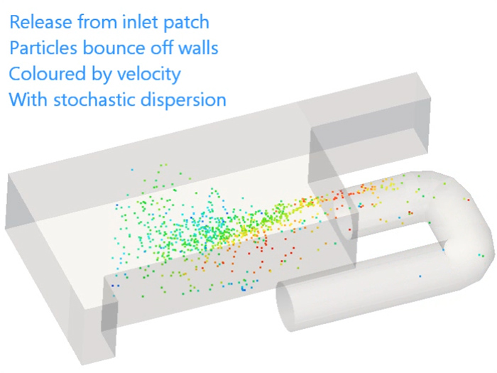
In both solvers the particles can be grouped together in parcels, in order to reduce the computational effort. These are injected into the simulation domain at patches, single points or point clouds. Parcels are defined by specifying the particle density, diameter distribution, release velocity, release rate and the weight or number of particles per parcel.

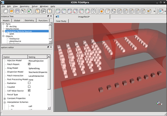
Set-up of Lagrangian Particle sources as line, plane and box in iconCFD GUI

The user can define how the particles react when they hit specific wall patches. They can bounce back, disappear or remain at their position on the wall. The user can also choose which forces are applied to the particles (gravity, pressure, virtual mass forces) and whether or not a stochastic dispersion is calculated using information from the pre-calculated turbulence fields.

All particle related settings are specified in the kinematicCloudProperties dictionary which contains information about:

– Physical properties of particles
– Particle injection
– Particle-wall interaction
– Modelled forces on particles
– Discretisation schemes for the LPT equations
– Dissipation Model

Click here to watch video about LPT functionality in iconCFD

The solvers output various volume fields (e.g.: particle number, concentration, mass, and velocity in each cell) and Lagrangian fields (e.g.: position and mean particle velocity vector, diameter, density of each parcel). For further post-processing the utility particleTracks can be used to create track lines in VTK format from the transient particle position results.

The iconCFD GUI is fully capable of writing the kinematicCloudProperties dictionary and setting up LPT simulations with uncoupledKinematicParcelFoam and incompressibleUncoupledKinematicParcelFoam.

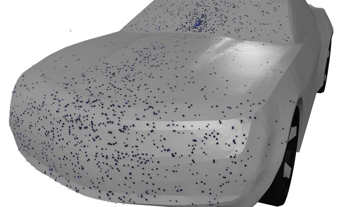
Click here to watch video of rain drops impacting on a moving car simulated with LPT in iconCFD

iconCFD 2.1.1 will soon be available. You will be informed in a separate email.

For further information please follow this link to contact us.

  •  

iconCFD News Cast – 02/2012 – Species Transport in iconCFD and the iconCFD GUI

iconCFD 2.1.1 introduces full support for new species transport solvers and accompanying models and boundary conditions:

– speciesTransportFoam is a transient species solver using a pre-calculated steady-state flow field.
– buoyantBoussinesqSpeciePimpleFoam computes a transient or pseudo-transient, incompressible, turbulent, buoyancy-driven flow along with a species transport solution.

Both solvers are capable of simulating the transport of multiple species. Two new dictionaries have been added:

– speciesTransportProperties: defines the necessary physical properties of the different species (i.e.: density, mass diffusion coefficients …).
– speciesSourceProperties: enables time dependant injection of species in specific regions of the simulation domain.

A new inlet boundary condition is available for simulating the recirculation from outlets to inlets (time delays, specific specie filters, additional sources). This can enable for example the simulation of building and aircraft ventilation systems.

Set-up of specie source in iconCFD GUI

With an additional feature in the fieldProcess function object the user can calculate and output the species concentrations in different units (kg/m3, ppm, …).

The iconCFD GUI allows full set-up of speciesTransportFoam and buoyantBoussinesqSpeciePimpleFoam cases, using the recirculation boundary condition, volumetric specie sources, and species transport properties.

Click here to watch video about newly implemented species transport functionality in iconCFD

Some example applications are simulating the dispersion of smoke, gases or pathogens in buildings and ventilation systems, the mixing of gases or fluids in industrial processes…

iconCFD 2.1.1 will soon be available. You will be informed in a separate email.

For further information please follow this link to contact us.

DATE CHANGES for Open Source CFD International Conference – Monday 29th October and Tuesday 30th October 2012

Due to an error by the Conference Hotel it is now necessary ICON, host of the Open Source CFD International Conference, change the dates of the conference, taking place in London. The new dates are now Monday 29th October and Tuesday 30th October, 2012.

The venue remains unchanged:

The Tower,
St Katharine’s Way,
London E1W 1LD
United Kingdom

To take advantage of the Early Bird discount, please click here. Offer ends 29th June 2012.

Abstracts are invited for a broad range of topics and should aim to highlight validated methods and breakthrough technologies. Works should demonstrate how adoption of open source CFD software is moving CAE process and business forward.

The following types of participation are all available at the event:

– Oral (Slides) Presentation + Written Paper;
– Oral (Slides) Presentation only;
– Poster Presentation + Written Paper;
– Poster Presentation only.

The paper submission deadline is 15 June 2012 and a submission form is provided at opensourceCFD.com.

We look forward to seeing you in London.

ICON enters strategic Sales Partnership with Dacolt in the Benelux

ICON Technology & Process Consulting Ltd. has formed a sales alliance with Dacolt to promote and support its CFD service, ICON FOAMpro in the Netherlands, Belgium and Luxemburg. ICON FOAMpro provides first class open source-based CFD solver and meshing tools, combined with industrial support embedded in a professional environment.

As a result of this partnership, Dacolt, a CFD consulting company which specialised in Combustion Modelling, will promote and provide support of ICON FOAMpro for Benelux customers. Furthermore, it will carry out CFD consulting business using ICON FOAMpro. ICON will back up the service providing training resources and offer its expertise where needed.

David Green, Commercial Director at ICON, said: “We are delighted to be working with Dacolt. Our organisations share similar values in best practice and customer service, enabling us to offer customers in the Benelux a compelling proposition. We welcome partnerships like these to better meet the needs of our customers in the local markets.”

About Dacolt

Dacolt offers software and services for CFD (Computational Fluid Dynamics) modelling of industrial combustion applications, by providing innovative tools and expertise to support its customers in realising their fuel efficiency and pollutant emissions design goals.

Dacolt and ICON jointly propose training courses in Combustion Modelling using OpenFOAM® technology

ICON, editors of ICON FOAMpro and experts in Open Source CFD technology and Dacolt, editors of Tabkin and experts in combustion modelling with CFD, have collaborated in the preparation and presentation of a three day training course in Combustion Modelling using OpenFOAM® technology.

The three day course covers the following topics:

Introduction to combustion modelling with CFD
Non pre-mixed combustion with reactingFoam solver
Pre-mixed combustion with XiFoam solver

An additional training day, An Introduction to OpenFOAM®, can be added upon request. This training course can also be given on-site.

The next training course is scheduled for June 20-22 in Maastricht, the Netherlands. For more details and to register, visit our training page.

iconCFD News Cast – 01/2012 – Support for baffles in iconCFD Mesh

In addition to the ability to create face zones in the volume mesh from STL or NASTRAN surfaces, iconCFD Mesh is now capable of splitting up face zones into two-sided internal patches enabling the user to create baffles of the following types:

– Face zones (a one-sided set of internal faces)
– Internal coupled cyclic patches which can be used for internal jump boundary conditions
– Two zero-thickness uncoupled patches, allowing separate boundary conditions on each side

Surface normals of different baffle types (left: face zone; centre: internal cyclic patch; right: two patches)

As part of the development advanced methods for snapping and creating surface layers were introduced to iconCFD Mesh.

– Feature line snapping is now also enabled for face zones and other baffle types.
– Boundary layers do not collapse when intersecting face zones any more. Now the mesher grows the layers up the baffles (even if they are curved) and assigns the appropriate side faces to the baffle patch.
– Layer growth up non-planar surfaces has been implemented as well as an advanced treatment for layers growing up concave corners. Both these features also increase the quality of the boundary layers growing up inlet, outlet and symmetry patches.

Boundary layers (left: collapsing when intersecting face zones; centre: growing up baffles; right: growing up surfaces in concave corners)

Automatic meshing of baffle surfaces was implemented in iconCFD Mesh for the purpose of increasing the flexibility of face zone usage, directly creating internal jump and cyclic boundaries as well as zero thickness walls with each side on a separate patch, while increasing mesh quality and surface layer coverage.

Example application of internal cyclic patch: STL geometry and volume mesh of a simplified car cabin geometry with internal jump boundary (marked red)

For further details please follow this link to contact us.