Month: October 2025
Streamlining Simulation Workflows with iconPlatform

At ICON Technology & Process Consulting, we continually develop and refine tools that enhance the efficiency, scalability, and accessibility of engineering simulations. One such solution is our iconPlatform — a browser-based environment designed to streamline the setup, execution, and analysis of simulation workflows.
Overview
iconPlatform provides a unified interface that integrates data management (object store), applications and ressources orchestration, process monitoring and post-processing exploration within a single web application.
This platform enables users to fully handle their simulations directly from their browser, eliminating the need for local software installation. It can be used from our provided instances, or deployed and self hosted on your environment.
Inputs Management
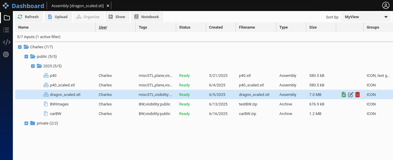
The Inputs tab allows users to upload, organize, and manage datasets that serve as inputs to simulation workflows. Any data can be uploaded here.
A built-in 3D viewer provides interactive exploration of geometries (like .stl and .obj files).
Tags are used as a flexible alternative to traditional folder hierarchies, allowing for more granular data classification and efficient retrieval in large-scale projects. More details will be provided in a future blog.
Application Management
Within the Apps tab, users can manage their applications: processing bricks ranging from small helper tools to distributed solvers.
Each one is defined using a json file describing its requirements, entry point, and options so the user can configure each run as needed.
Applications can be deployed seamlessly across HPC system, leveraging Slurm, LSF, or any workload manager of your choice if needed.
The platform’s templating system exposes contextual metadata (e.g., simulation parameters, job IDs, environment variables), allowing information to flow in between chained applications.
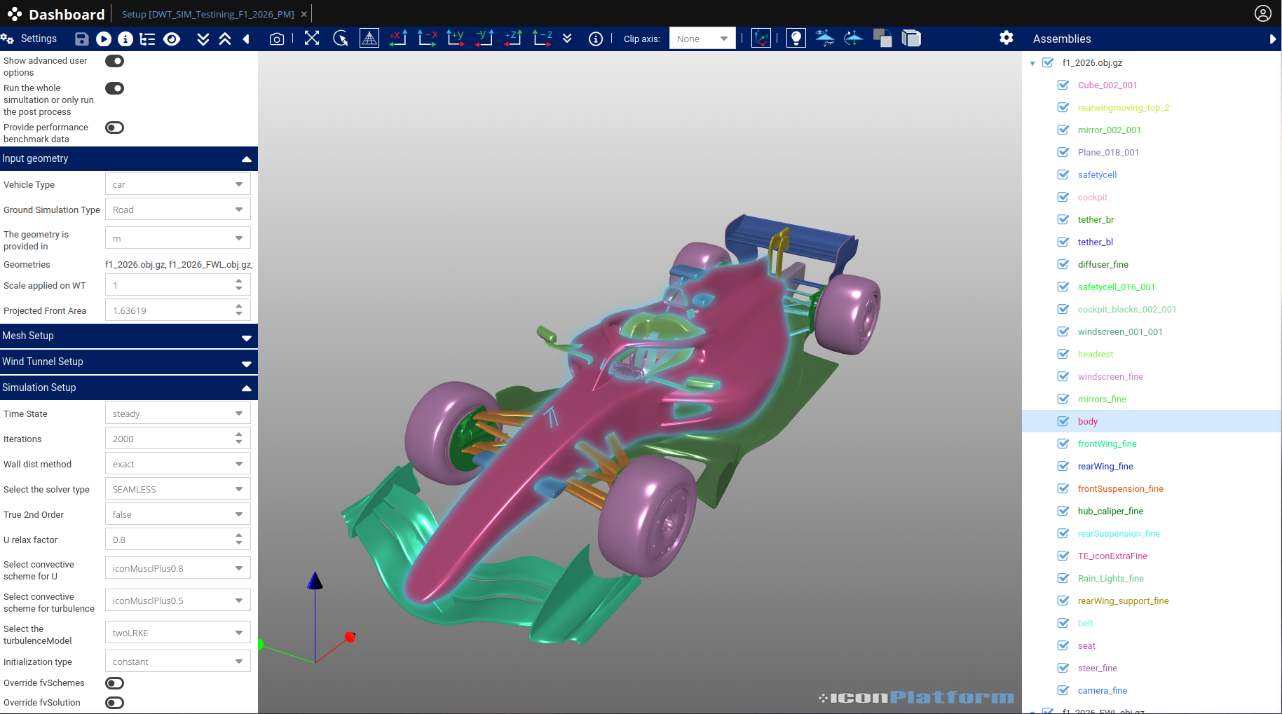
Process Execution and Monitoring
The Process tab serves as the operational core of the Platform. Here, users combine Inputs and Apps to define workflows, allocate computational resources, and monitor execution in real time. As for the input tabs, processes can be label with tag and displayed using customer defined hierarchies, allowing to classify and filter a large amount of execution easily. The platform provides native integration with job schedulers, fully transparent to the end user.
Result explorations
Once the processing is done, users can leverage built-in visualization and analysis capabilities, including:
- Interactive 3D visualization of simulation domains
- Interactive tools to explore database of screenshot
- Chart and tables using interactive web components
These visualization tools are optimized for both performance and usability, enabling rapid iteration between simulation setup and analysis.
Design philosophy
The iconPlatform architecture is intentionally designed to minimize server-side overhead. Once primary compute tasks (such as mesher, solver runs or post-processing operations) are completed on target HPC clusters, subsequent analyses are executed client-side within the browser environment.
This approach ensures that no additional cluster connections or HPC resource allocations are required during case analysis, leading to more predictable compute costs and improved responsiveness for end users. As a result, engineers can interactively explore and analyze simulation results without incurring further server-side load or queue times.
Related Products
A generic post-processing application designed to automate ParaView pipelines via lightweight JSON definitions is also available. It brings the full post-processing power of ParaView with a simple integration into iconPlatform.
The CFD analysis showcased in this article was created entirely within iconPlatform, demonstrating the seamless integration between data management, computation, and visualization. iconPlatform is not limited to CFD workflows.
Learn More
For more information regarding iconPlatform or iconCFD Post and how it can accelerate simulation workflows and productivity, contact us at:
https://www.iconcfd.com/contact-us/
WCIT-ICON Space Webinar Recording access request
ICON Publications and Presentations
Thank you for your interest in ICON.
You can find some of our Publications and Presentations below:
- ICSC 2015-Aerodynamics Aeroacoustics Development at Audi
- ECCOMAS 2016-An Integrated Framework for Wrapping and Mesh Generation of Complex Geometries
- SAE 2016-Adjoint-Driven Aerodynamic Shape Optimization Based on a Combination of Steady State and Transient Flow Solutions
- SAE 2017-An Extensive Validation of an Open Source Based Solution for Automobile External Aerodynamics
- SAE 2018-Combined Drag and Cooling Optimization of a Car Vehicle with an Adjoint-Based Approach
- SAE 2018-Industrial Application of an Advanced Elliptic- Blending Turbulence Model for Wheels Aerodynamics Analysis
- FKFS 2021-Efficient CFD methods for assessment of water management
- FKFS 2023-Advanced CHT Simulations for Brake Disc Cooling Applications Using iconCFD
- SAE 2025-Targeting Enhanced Numerical Stability, Solver Performance & Accuracy on Industrial Applications
- FKFS 2025-CFD Simulations of Vehicle Self-Soiling
ICON & WCIT Webinar Content: Software Enabled Space – How Simulation accelerates Space for Good

Please find below the recording and the content
of the ICON Webinar in association with WCIT :
“Software Enabled Space: How Simulation Accelarates Space For Good”
Protected: ICON Introduction – Manthey
Protected: 2025-10 ICON Introduction
ICON Presented at the 2025 FKFS Conference on Vehicle Aerodynamics and Thermal Management
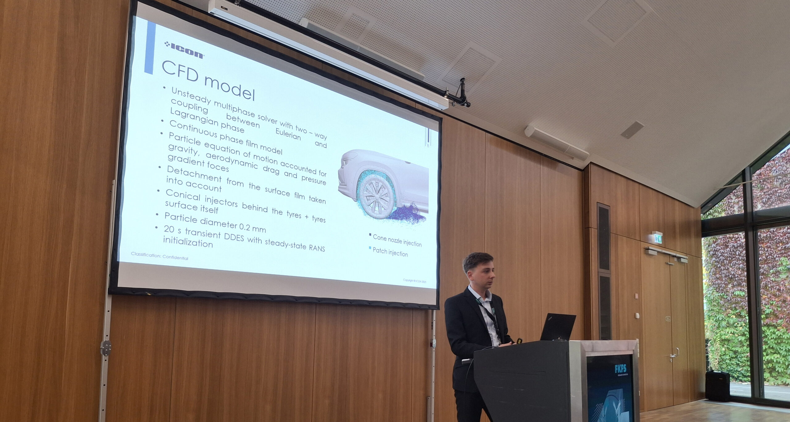
It was great to take part in this year’s FKFS 𝗖𝗼𝗻𝗳𝗲𝗿𝗲𝗻𝗰𝗲 𝗼𝗻 𝗩𝗲𝗵𝗶𝗰𝗹𝗲 𝗔𝗲𝗿𝗼𝗱𝘆𝗻𝗮𝗺𝗶𝗰𝘀 𝗮𝗻𝗱 𝗧𝗵𝗲𝗿𝗺𝗮𝗹 𝗠𝗮𝗻𝗮𝗴𝗲𝗺𝗲𝗻𝘁, where Martin Sevcik presented 𝗜𝗖𝗢𝗡’s collaborative work with Škoda Auto on:
𝑪𝑭𝑫 𝑺𝒊𝒎𝒖𝒍𝒂𝒕𝒊𝒐𝒏𝒔 𝒐𝒇 𝑽𝒆𝒉𝒊𝒄𝒍𝒆 𝑺𝒆𝒍𝒇-𝑺𝒐𝒊𝒍𝒊𝒏𝒈
The presentation was very well received and drew considerable attention, highlighting how advanced CFD methods using iconCFD® are helping to better understand and address soiling effects on ŠKODA vehicles — a key consideration in both design and performance.
A heartfelt thank you to FKFS for once again organising a well-executed and insightful event. It’s always a pleasure to engage with fellow experts and innovators in the automotive community.
We look forward to continuing the conversation and driving innovation forward.
You can find Martin’s presentation below:
Extending Accurate Aerodynamic Predictions – Rain Soiling and External Water Management
External Water Management (EWM) is crucial for ensuring driver comfort and safety, particularly under adverse weather conditions. Effective EWM reduces visibility issues, prevents water accumulation on critical surfaces, and limits rain-induced soiling of the vehicle exterior. Optimizing EWM around the A-pillar is inherently challenging due to structural considerations, as well as aerodynamic and acoustic performance requirements. To address these challenges efficiently within short development cycles, ICON now provides the ability to simulate these conditions, accurately predicting A-pillar overflow and the extent to which it will affect side window visibility. This is achieved using complex physical models made available within the iconCFD L2P module that account for mass and energy transfer between three distinct phases — air, rain droplets, and the surface water film.
Aerodynamic Foundation and Simulation Approach
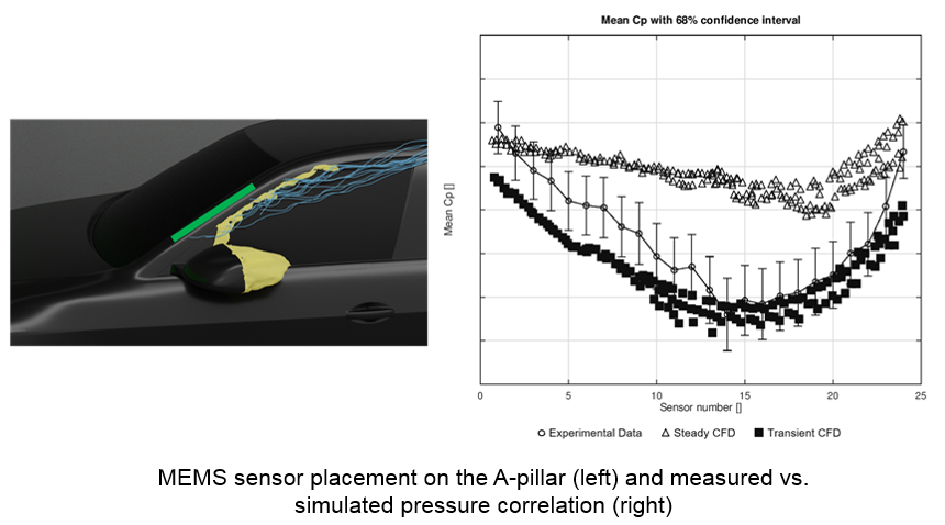
Accurate airflow prediction is essential for capturing the water transport and overflow around the A-pillar. Detached-Eddy Simulation (DES) is more accurate than steady RANS for predicting the unsteady flow structures near the A-pillar, as confirmed by Micro-Electro-Mechanical Systems (MEMS) sensor data.
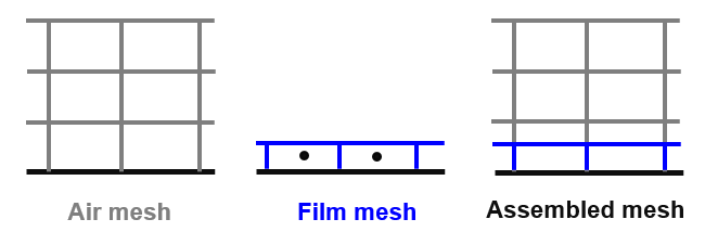
The surface water film is represented using a thin-film approach with a single-layer mesh extruded from the car surface. On a detailed vehicle geometry, features of interest can be as small as ~1 mm. A robust, automated local mesh refinement strategy is crucial to achieve this resolution efficiently without generating an excessively large number of cells that would unnecessarily increase simulation time. iconCFD Mesh provides the right balance of automation, speed, and geometric accuracy allowing the generation of a mesh including the film to air coupling interface in less than an hour on a full vehicle.
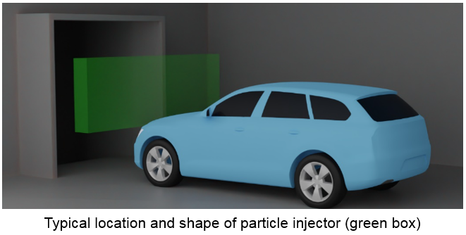
Rain is modeled using Lagrangian spherical particles with diameters ranging from 0.2 to 2 mm, injected ahead of the vehicle within a defined box-shaped region. Advanced wall interaction models account for droplet absorption, rebound, spreading, and splash, allowing smooth transition from discrete droplets to surface water film.
One-way coupling between air and water film is employed. For surface contamination resulting from direct particle impacts, stronger coupling with the air phase can be required if the Stokes number is high, indicating significant particle–air interaction. In the context of A-pillar overflow, however, this simplified approach is sufficient and provides a good balance between computational efficiency and physical accuracy.
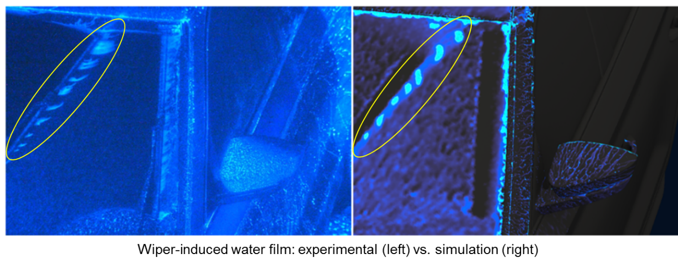
Wiper effects are included via a purposely-built parametric immersed boundary method (IBM), which introduces wiper-induced water flux without having to explicitly move the wiper geometry. This innovative approach eliminates the overhead of traditional IBM or overset mesh methods, increasing solver runtime by only ~9% compared to simulations without wipers. Despite its simplicity, it provides a solution that is not only efficient but realistic.
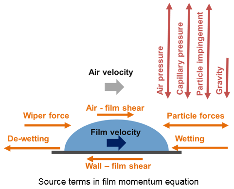
Modeling the Water Film – Complex Forces in Action
The water film is governed by forces acting tangentially and normally on the substrate surface (car surface), originating from airflow, wipers, gravity, and other effects. The model also relies on empirical coefficients, which are carefully calibrated to reproduce correct behaviour under different rainfall and airflow conditions. Accurate resolution of the airflow, especially in the near-wall region, is critical, as it directly influences several source terms and ultimately the fidelity of the water film simulation. The numerous source terms at play make the model inherently complex and can pose challenges from a numerical stability standpoint. These challenges were overcome in the solvers and schemes implemented in iconCFD.
Predicting Side Window Soiling
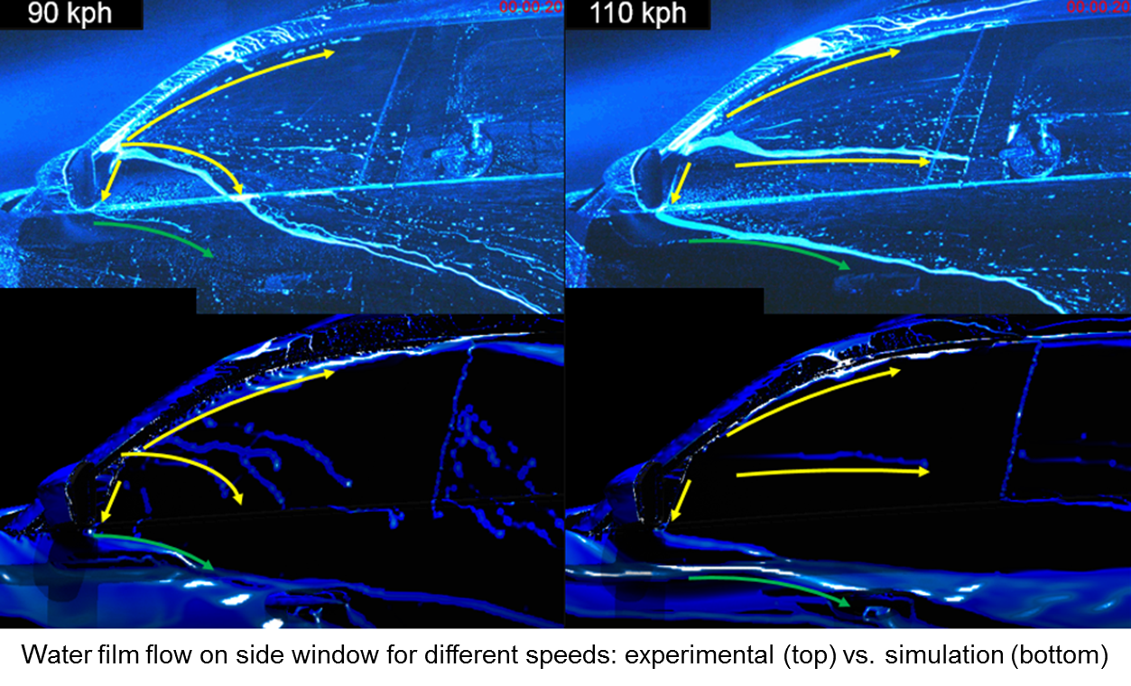
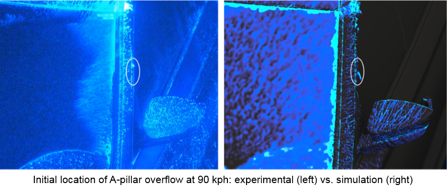
The method was validated on the prediction of A-pillar overflow and water transport on the side window of a test vehicle provided by Škoda Auto at vehicle speeds of 90, 110, and 130 kph. The simulations represent 10 seconds of real-world rainfall. Comparisons with wind tunnel data show that the model predicts the location of the “breaching point” on the A-pillar accurately. Beyond this point, the water film on the side window, including streaks and flow patterns, is well represented. Overall, the methodology provides qualitatively satisfactory predictions of water transport and accumulation patterns.
Main Takeaway
Using iconCFD based EWM methodology we are able to augment high-fidelity aerodynamic simulations with accurate prediction of A-pillar overflow and side window soiling. Rainfall behaviour, film transport and wiper effects, are all taken into account without adding significant cost over the base simulation.
For readers interested in more technical details, the methodology is further described in the paper, “Efficient CFD methods for assessment of water management” co-published with Škoda Auto.
Acknowledgements
ICON gratefully acknowledge the close collaboration and support of Škoda Auto a.s., including access to analysis results, vehicle geometries, and experimental data.